


Wiki - Controller
Controller choices, Calibration and Configuration for best experience
Controller Choice
Explore here all the different Controller options compatible with AeroSIM-RC(Since version 6.0, AeroSIM-RC supports any joystick device, with the USB interface working as a license dongle)
If you do not have any Controller
We recommend the AeroSIM RC pack with controller. This pack has everything you need to start your training, including a Transmitter and the corresponding Receiver to allow wireless operation. The simulation is controlled wirelessly without any cable between the Transmitter and the computer. 
If you have a RC Transmitter with Trainer Port
A wide variety of RC transmitters are available from RC shops. Most manufacturers (FrSky, Futaba, FlySky, Graupner, Spektrum, Hitec, JR, Walkera, MULTIPLEX, RadioLink, etc.) provide a Trainer Port (also called DSC socket, or PPM output) in their transmitters which output a PPM signal that contains the position of the sticks. This PPM signal is processed by the AeroSIM RC USB interface, which presents the transmitter as a USB joystick to the computer.Jack
If the connector of the Trainer Port in your transmitter is a female 3.5mm mono jack, then the jack in the AeroSIM RC USB can be connected directly. 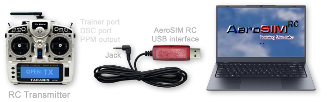
Using an Adapter
If the Trainer Port connector in your transmitter is not a female 3.5mm mono jack, then an adapter is required.We provide adapters for most popular brands: Futaba, Hitec, Graupner, Multiplex, FlySky, WFly, RadioLink.

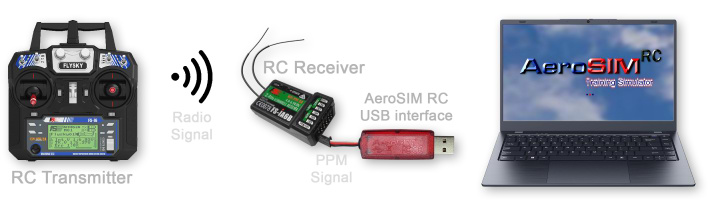
If you have a Receiver with PPM output
Some RC Receivers can output the PPM signal that contains the positions of the controls. In this case, the simulation can be controlled wirelessly without any cable between the Transmitter and the computer.Examples of wireless connection using different receivers
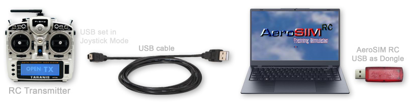
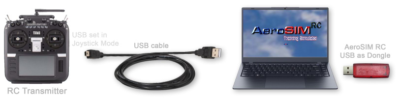
If your Transmitter has Joystick Mode
Some RC Transmitters have a USB port that can be set in Joystick Mode (RadioMaster, BETAFPV, Taranis, etc.)In this case, the AeroSIM RC USB interface is used only as a license dongle.

If you have a USB Simulator Controller
Some RC manufacturers like Dynam or FlySky sell inexpensive USB RC Flight Simulator Controllers, for simulator use only, which look like a conventional RC Transmitter. 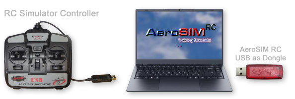
If you have an InterLink DX Simulator Controller
Spektrum InterLink DX Simulator Controller can also be used with AeroSIM-RC 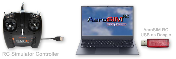
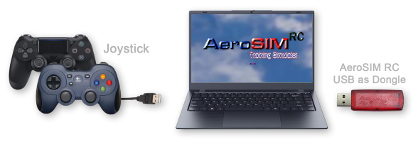
If you have any Joystick
Any joystick can be used in AeroSIM RC, for example PS4 and XBox controllers.However, we strongly recommend to use a proper RC controller since most joysticks do not have the quality required for good training.
If you have a DJI controller
DJI controllers only work with DJI systems. However the old Phantom 2 Controller (models NDJ6 and NPVT581) is compatible since it has a PPM output at the back. It requires an adapter available from us. 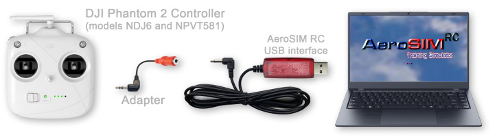
Help!
Please contact us if you need help.USB Interface
AeroSIM-RC is supplied with a USB interface.
The USB interface has two functions:
- connects the RC Transmitter to the computer,
- and also works as a license dongle.
Flavours
The AeroSIM-RC USB Interface is available in two flavours:

|

|
|
USB interface for wired operation. |
USB interface for wireless operation. |
Optional adapters are available for RC transmitters which require a different connector.
Red LED inside the USB case
The red LED inside the USB case provides the following information:
| Red LED | Meaning |
|---|---|
| ON | Normal operation. The USB interface is receiving a signal from the Remote Controller. |
| OFF |
The USB interface is NOT receiving any signal. For example, when the Remote Controller is:
|
| Flashes 4 times | The USB interface has just powered up (when plugged in a USB port). More information |
| Flashing | The USB interface is in a special mode for entering license codes. Please, follow the instructions on the screen to exit this mode. |
Wireless Control
AeroSIM-RC can be controlled without any wires between the RC Transmitter and the computer.
Your RC Transmitter is already a wireless controller, so why not use it wirelessly with the simulator?

A receiver with PPM output is required. SBus receivers require a SBus to PPM converter.
Examples

Example of wireless operation using a PPM receiver FlySky FS-A8S.

Example of wireless operation using a PPM receiver FlySky FS-iA6B.

Example of wireless operation using a Graupner PPM receiver.

Example of wireless operation using a FrSky compatible D8 receiver with PPM output.
SBus Receiver
If the receiver has SBus output, you can use a SBus to PPM converter.

Example of wireless operation using a spare DJI Phantom 2 receiver,
which has a SBus output that is converted to PPM
Controller FS-i6S
AeroSIM-RC is available as a pack with the Remote Controller FS-i6S.

Configuration
See the step by step configuration instructions for FS-i6S.
Manual
Find more information about the FS-i6S controller in the manual.
| Downloads |
|---|
| FS-i6S Manual - English |
| FS-i6S Manual - French |
Controllers Screen

In the Controllers screen you can:
- Select the active Controller.
- See a list of connected devices.
- Start the Controller Calibration
- Enter the Configuration Screen
- Delete and Create new Configurations.

Controller Calibration
The simulator needs to learn the end position and center position of each stick in your Controller.
The Calibration process consists in moving each control (joysticks, switches and knobs), while the simulator learns their center and end position values.
You can tell that the calibration is wrong if the motor does not start, or if the aircraft drifts during flight.
How to Start the Calibration process
The Calibration process is started from the Controllers menu.
Click on the "Calibration" button of the Controller you want to Calibrate:
Calibration Step 1: Learn end positions
Move the controls to their extreme positions (full left, full right, full up and full down), and all switches, and pots to their end positions.
For fun, there are some ducks on each control. Shoot them by moving the controls to their end positions.
Click "Done" to continue to step 2.
")
Calibration Step 2 - Learn center positions
Please, let the sticks return to the center by means of their auto centering springs, leave any 3-position switch in its middle position, and move any potentiometer with center detent to its center.
If the throttle stick in your controller has no auto centering spring, then leave the throttle stick at the bottom position.
Click "Done" to continue to step 3.

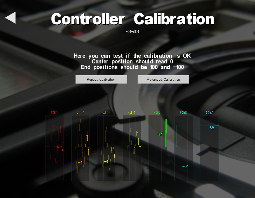
Calibration Step 3 - Verification
Calibration is complete. Let's test it.
The number in each channel graph is the calibrated value (between -100 and 100).
If the calibration is successful, the number should reach -100 and 100, and stop exactly at 0 anytime the control is centered.
In this screen you can move the controls and watch the calibrated result.
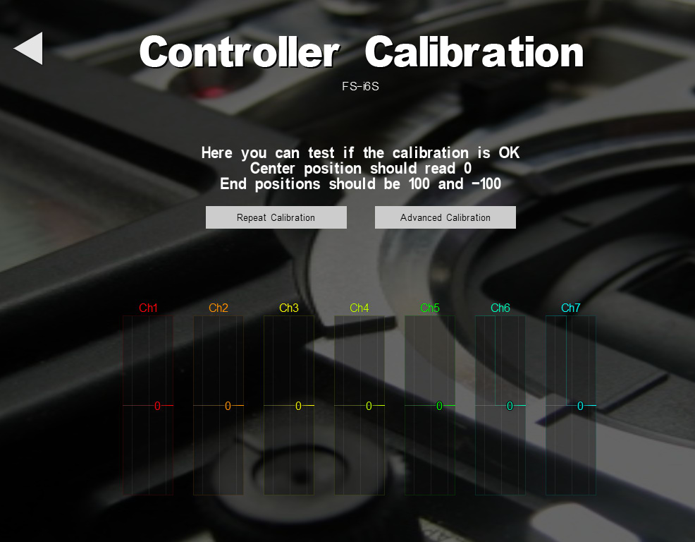
After a successful calibration, all controls should read 0 when centered:
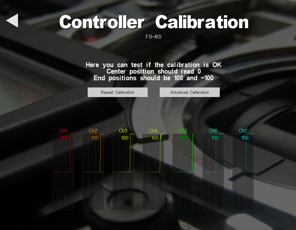
After a successful calibration, all controls at one end position should read 100:
After a successful calibration, all controls at the other one end position should read -100:
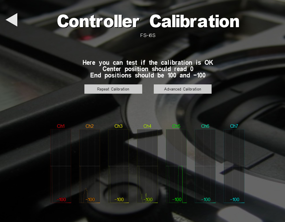
If the Calibration test fails (come channel not reaching 100 and -100, or not centering at 0), you can either click on "Repeat Calibration" or try the "Advanced Calibration".
Advanced Calibration
In the Advanced Calibration screen you can set the calibration values manually.
The advanced calibration is useful if you want to fine-tune a calibration, if a particular channel is noisy and does not calibrate well, or if it has a deadband you want to eliminate.
Center
The check box "Center" should be ticked in autocentering controls (e.g. spring loaded sticks), controls with a center detent (e.g. potentiometers with center detent), or 3-position switches.
In the image below, channel 3 represents a throttle stick which has no centering spring, as used in airplanes.
Deadband
Good quality controls provide highly repeatable readings, always giving the same value at their central position. However, some joysticks and some specific controls (e.g. potentiometers with detent) may show poor repeatability at their central position.
The deadband is the range of possible landing values when a control is at its center position.
In this example, channel 5 represents a potentiometer with detent used for camera zoom. The deadband is defined as the interval [121, 141]. Any value in this interval will be considered to be at the exact center. If this control were used without deadband, the camera zoom could slowly drift because of poor center repeatability.

Controller Configuration
In the Configuration screen, the aircraft functions (roll, pitch, landing gear, flight mode, camera pan/tilt, etc.) are assigned to a specific Control (stick, switch, knob) on the Controller.
How to Enter the Controller Configuration screen
The Configuration screen is entered from the Controllers menu.
Click on the "Configuration" button of the Controller you want to Configure:
Function Groups
The aircraft Functions are grouped in sections. Click on the triangle to expand/contract each section.
Here you can also change the Configuration name.

Primary Controls
The Primary Controls are the two sticks on the controller.- Primary Controls are always enabled, for this reason the 'enable' box at the left is always ticked.
- The sticks are used to change the pitch, roll, yaw and throttle of the aircraft.
- There are 4 possible Stick Modes. The most common Stick Modes are 2 and 1:
- Mode 2 has the throttle on the left stick.
- Mode 1 has the throttle on the right stick.
- If the controls move in the wrong direction, check the REV box to reverse the direction.
- When the Controller is correctly calibrated, the stick center position should read 0, and the stick end positions should be 100 and -100.

Flight and Control Modes
Each aircraft has different flight modes and control modes available.- Make sure the 'enable' box at the left is ticked if you want to operate this function from the controller.
- Each aircraft implements a different set of Flight Modes. The Flight Modes in multirotors usually include Manual, Attitude and GPS. Airplanes have different stabilization modes such as altitude hold and autolevel.
- Course Lock is a Control Mode used in multirotors. In Course Lock mode, the direction of Pitch and Roll is not made by 'Front' definition, but by an absolute reference heading.
- ALT Hold is an autopilot that holds the altitude.
- RTH stands for the Return To Home function available in most multirotors.
- Throttle Hold is used in helicopters. Function Throttle Hold will set the engine to Idle to practise Autorotation

Camera and Gimbal Control
Each aircraft in AeroSIM-RC is equipped with one or more onboard cameras and gimbals with specific stabilization and control options, which can be configured per aircraft.- Camera Pan and Tilt and Roll. Most cameras are mounted on stabilized gimbals with motors that control the camera Pan and Tilt and Roll.
- Usually, the camera Roll is automatically controlled by the gimbal, but it can also be controlled manually in some multirotors.
- Camera Zoom is also available in some cameras, others have a fixed zoom.
- Stabilization: Gimbals can be manually controlled, and have different ranges of motion. Stabilization can be turned on and off.
- Gimbal Center: With gimbals that can pan up to 360 degrees in both directions, centering the gimbal resets the pan angle.
- Camera #: When several cameras are defined in an aircraft, the Camera Selection control is used to select the camera shown in the View.
- Photos can be taken of the scene as viewed by the camera and saved as jpg files in folder C:\Users\Public\Documents\AeroSIM_RC\snapshot
- All camera parameters (pan/tilt/roll/zoom speed, limits and stabilization) can be edited in the Aircraft Editor

Aircraft Systems
- Some airplanes have Retractable Landing Gear, Flaps and Wheel Brakes
- The Wheel Brakes are usually controlled with the same channel as the Elevator, so the brakes are operated when the Elevator is pushed.
- Aircraft Lights can be turned on and off
- Parachute release for experiencing the flight termination, and most importantly, the effect of the wind after deployment.

Simulation Control
The simulation can be conveniently restarted from the controller.- Reset Aircraft on the ground after a crash or at will to repeat an exercise.
- Second Chance is a time travel to a few seconds earlier in the aircraft trajectory.
- Mouse with TX: The computer mouse cursor can also be moved with the controller sticks. Useful if you are using the simulator with FPV googles and want to use mouse from the controller.

Plugin Control
Plugins are written by users with programming skills. Plugins in AeroSIM-RC can simulate an OSD, or an autopilot, or provide a virtual aircraft sensor and telemetry data to some Hardware In the Loop for testing and development.
Keys
Most aircraft functions in the simulator can be operated from the keyboard and mouse.
The key assigned to each function is displayed when hovering the mouse over it.
Redefine Keys
All functions in AeroSIM-RC can be activated from the computer keyboard. For example, to restore the aircraft to the initial position on the runway, press Space.
The key assignments can be changed from Main Menu / Controls / Define Keys
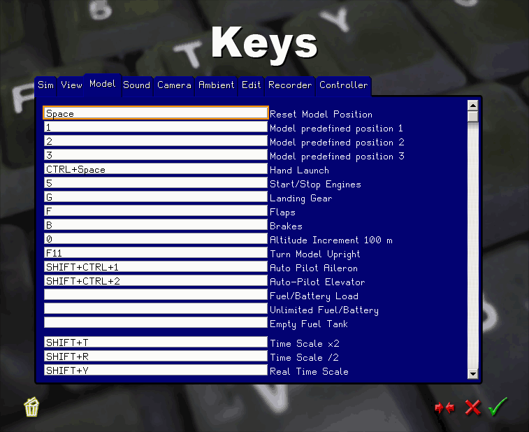
Key assignment panel
Mouse with TX
Mouse emulated with the Remote Controller
You can operate all simulator functions from your Remote Controller. No mouse, no keyboard needed.
Select a Remote Controller channel to activate the Mouse Control at the channel configuration screen.
This is the cursor displayed when the mouse emulation is activated:
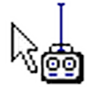
This Cursor is shown when mouse is controlled by the Remote Controller sticks
Wiki - Controller
Controller choices, Calibration and Configuration for best experience