


Wiki - Scenarios
Available Scenarios and How to create your own scenario
Scenarios
You can open the Scenario select dialog from the Bottom Menu Bar


Available Scenarios

Optional add-on scenario for specialised training.
Intro
After the scenario is loaded, an introductory tour around the scenario will be started.
To skip the scenario tour, press ESC, Enter, Space bar or a mouse button.
User Generated Scenarios
With the Scenario Generator, you can create new scenarios in AeroSIM-RC from a satellite image of your flying site.
The user created scenarios are useful for FPV flights in order to familiarise with roads, rivers, fields and buildings around the flying area.
How to Create Scenario
How to create a new scenario from a satellite image
Building a new scenario from a satellite image is a very satisfying job when finally overflying your own flying site in the simulator. It may seem a complex process, but a great effort has been done to make it user-friendly, and once the satellite image is obtained, the rest is easy.
A Scenario consists of a 3D grid over which the satellite image is laid.
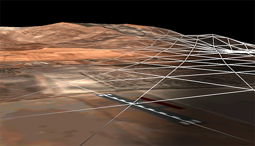
3D grid from a scenario under construction
Brief Instructions to create a Scenario
Get the image and the reference coordinates as described in the next section and then go directly to build the scenario in the simulator.
Prepare the Satellite Image
Required data
| You need |
|---|
| The satellite image |
| Two coordinates |
| Some elevation files (optional) |
| Requirements | |
|---|---|
Size |
The recommended size is about 8.000 x 8.000 pixels for an area of 5x5 Km to 15x15 km. The image can be rectangular. |
File Format |
The image file format must be JPG. |
Coordinates |
The image must be oriented with the North up. Choose two locations in the image (a house, tree, etc.) and write down their coordinates (latitude and longitude) The locations should be far away from each other to improve the accuracy of the calculations. |
Terrain Elevation |
Download the Elevation Data files suggested in Step 4. |
How to capture the image from Google Earth
To get the recommended 8.000 x 8.000 pixels image, you will need to capture several images and stitch them together
In Google Earth
- Navigate to the area of interest.
- Disable the elevation to get a flat terrain:
- Google Earth 6: Tools / Options / Terrain Quality / unmark the check box 'Show Terrain'.
- Google Earth 7: Unmark the Layer 'Terrain'.
- Tilt down to obtain a flat and vertical view of the terrain (Control key + Mouse Up).
- Set the view to North (by clicking on the 'N' mark of the compass).
- Do not change the height when capturing the images, so they can be joined together later on.
- Pan the view to get several overlapping images following a square pattern:
Stitch the images together
- Using the free tool Microsoft ICE (Image Composite Editor)
- or, manually using an image editor such as Gimp or Photoshop
Steps to create a Scenario
Once the image is ready, start the tool from Top Menu / Create FPV Scenario
Follow this process to generate a new scenario from a satellite image:
- Select the image
- Georeference the image
- Choose the Aircraft Initial Position
- Paint or Import the Terrain Elevation
Press the red cross at the bottom left of the screen to exit the tool. Any progress you may have made will be stored and recalled when the same image is selected.
Step 1: Select the Image
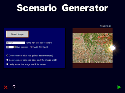
Step 1: Select the Image file
Select the image file
Push "Select Image" button to open a dialog where you can select the jpg file of the terrain you prepared.
Name for the new scenario
Write a name for the new scenario
Sun position
This value is the position in degrees where the Sun will appear. 0 for North, 90 for East.
Select a georeferencing method
The scenario generator needs to know the Scale and the Coordinates (latitude and longitude) of the image. This is called georeferencing an image. In order to supply this information, there are three options:
- Georeference with two points (recommended)
- Use this method is you know two points of known coordinates (lat, long) on the image.
- For better accuracy, the points should be as far from each other as possible.
- Georeference with one point and the image width
- This method uses one point of known coordinates (lat-long) on an image with the North up, and the image width in metres.
- I only know the image width in metres
- This method does not georeference the image, since latitude and longitude coordinates are not supplied. However, a scenario of a given size can be easily generated. The image width is the distance in metres between left and right sides of the image.
- For the last two options, the image width needs to be supplied. The image width is the distance in metres between the left and right sides of the image.
Step 2: Georeference the image
Place the marks over the points which coordinates you already know, and enter their latitude and longitude. The points should be chosen to be as far away from each other as possible.
The Latitude format is:
First letter N or S, space, degrees, space, minutes, space, seconds with decimal point.
For example N 37 8 48.33
The Longitude format is:
First letter W or E, space, degrees, space, minutes, space, seconds with decimal point.
For example W 5 47 10.43
Move the image and the points with the mouse left button.
Zoom in and out with the mouse wheel, or using the "Page Up" and "Page Down" keys.
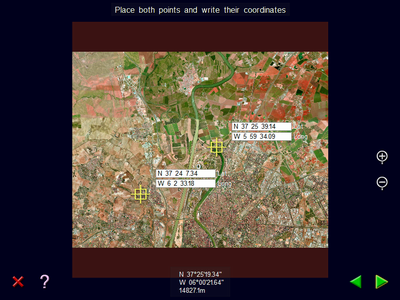
Step 2: Georeference the image
Step 3: Choose the Aircraft Initial Position
Place three Aircraft Initial Positions wherever you like on the scenario, indicating the heading for each position.
Zoom in and out with the mouse wheel, or using the "Page Up" and "Page Down" keys.
Move the image and the points with the left mouse button.
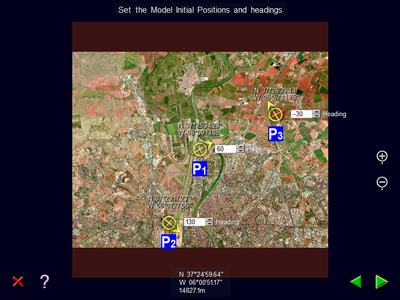
Step 3: Aircraft initial position
Step 4: Add Terrain Elevation
Make mountains and valleys
The Terrain Elevation can be applied either by:
- Importing elevation data files (*.hgt)
or - Painting the elevation with the mouse.
Step 4: Import or Paint the Elevation Map
Recommended Option: Importing Elevation Data Files
You can apply the elevation from terrain elevation files with format .hgt
The .hgt elevation files can be freely downloaded from https://srtm.kurviger.de/SRTM3
Please, contact us if you want us to email you the hgt files.
The elevation filenames required for your scenario are listed on the left side of the screen, for example, S24W048.hgt
Download and copy the .hgt files to the image folder, then click on the World Elevation Map button to apply the elevation data.
If the .hgt filename is displayed in red, it means that the file is missing.

Button to apply real elevation data to your scenario.
After applying the elevation, you can retouch the elevation by painting on top. For example, you can flatten the take off areas.
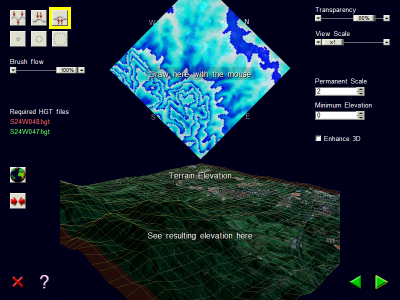
Second Option: Painting the elevation
Paint with the mouse on the top image, and watch the results in the 3D representation below.
The 3D can be rotated with the left mouse button, and zoomed with the right button.
Elevation Painting Controls on the left
- Brushes to paint the terrain elevation
- Levels terrain (keep pressed the SHIFT key to use this function)
- Rise terrain
- Lower terrain (keep pressed the CONTROL key to use this function)
- Brush sizes
- Use the mouse wheel to change the brush size
- Brush flow
- This is the speed at which the terrain rises when the elevation map is drawn
- Apply Elevation button
- Applies the elevation from the downloaded elevation files
- Reset button
- Clears the elevation map. No confirmation asked!
Elevation Painting Controls on the right
- Transparency
- Transparency between the image and the elevation map
- View Scale
- Exaggerates the heights on the 3D view. Useful while editing to better visualise the elevation.
- Since this scale value is not taken into account when the scenario is generated, it must be set to 1 to see the final result before proceeding to the next step.
- Permanent Scale
- The Permanent Elevation Scale is used to generate a scenario with exaggerated heights.
- Minimum Elevation
- This value is the elevation of the lowest point of the scenario expressed in metres. Will affect the altitude indicated in the flight instruments.
- Enhance 3D perception
- Enhance the 3D perception by applying a wavy motion to the scene.
Final Step: Generating the Scenario
Press the button "Generate Scenario", or enter the Expert Mode for more settings.
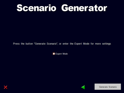
Ready to generate the scenario
Expert Mode settings
The Expert Mode allows to edit the settings related to the terrain mesh size and the downsizing of the textures.
The changes in the settings are reflected in a drawing with colours and lines on the right side of the screen.
The colours show the reduction in size of the textures:
1/1 size White
1/2 size Yellow
1/4 size Magenta
1/8 size Red
The lines represent the elevation grid density.
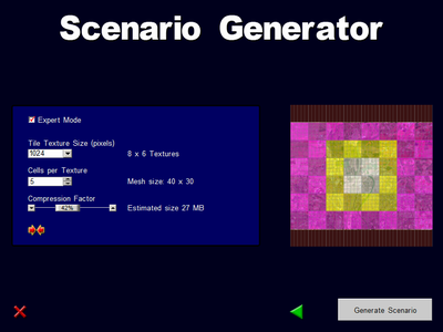
Expert Mode extra settings
Warnings
When the advanced settings are modified from the recommended values, there may appear Yellow or Red messages. A Yellow message means that the value is near its limits, and a Red message prevents the generation of the scenario. Contact us if you need to override these limits.
Tile Texture Size (pixels)
The image will be sliced in small tiles of this size.
Cells per Texture
Each texture is divided in a number of square cells, and the terrain elevation is applied to each cell vertex.
Compression Factor
This parameter reduces the total size (in Megabytes) of the 3D terrain model. The quality will be reduced on the edges of the image.
Recommended values
Push this button to reset to the recommended values
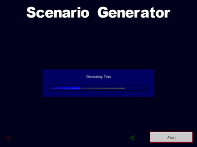
Generating the Scenario
The scenario generation can be aborted any time by pushing the button "Abort"
Once the new scenario is generated, the simulator will load it automatically.
Troubleshooting
If an error occurs during the generation, check that there is enough free space in the hard disk. For example, to process an image with 10.000 x 10.000 pixels, 250MB free disk space is required.
Please contact us if you need help with the Scenario Generator.
Wiki - Scenarios
Available Scenarios and How to create your own scenario